!--Start of Archive--!
Well, the four channel Rheobus has a couple quad op-amps, along with some caps and resistors, smack dab in the center of the PCB and the only reason I can think to have those there would be to act as an oscillator (timing circuit) for PWM regulation. If you measured the output with a multimeter, it would indicate that the actual output voltage was changing when the knob is turned but all it's showing you is apparent voltage (since the DMM really doesn't refresh fast enough to know what's going on... you'd need an oscilloscope to see that).
I'll see if I can borrow an o-scope from someone either this weekend or next week and put together a little video showing the output of various fan controllers.
Erm, as a bit of an update... I think that I'm going to have to re-evaluate my statements regarding the Sunbeam Rheobus...
Margaret came up to visit this weekend and we managed to pull an ancient oscilloscope outta her parent's attic to test a few fan controllers with. What we found was interesting but kinda confusing.
As I mentioned previously, I had assumed that the Sunbeam Rheobus was using some form of PWM due to the components which are on the PCB; however, when we hooked the controller up to the o-scope, we got something that looked like this:
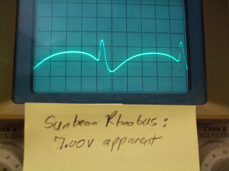
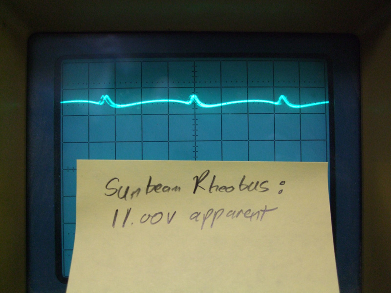
Hmmm, thought us... that doesn't look like any sort of PWM that we've seen before. Then we remembered that the fan which was hooked up to the channel we were testing would act as an inductive load and, therefore, what we were seeing was feedback from said fan. Hooking a pot up to the controller (resistive load) resulted in the output looking like a flat line (straight DC output).
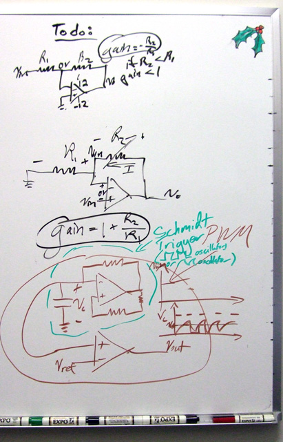
So, what does this mean? Well, it means that, assuming the old o-scope wasn't acting funky, the output from the Rheobus is not a PWM signal, it's just straight DC voltage. However, that still doesn't explain why we were able to start fans at lower voltages with my lab PSU (or a computer PSU and some resistors to give the desired voltage drop) than the Rheobus, it doesn't explain why they are using two op-aps per channel in the Rheobus (because, as Margaret demonstrated on my white board, you can create a PWM fan control circuit with just two op-amps), and it doesn't explain why it looked like they were using one of the op-amps as an integrator (which would imply some kind of PWM). Due to the unanswered questions, Margaret is taking a couple controllers back down to Cal Poly with her, where she has access to better equipment and will more easily be able to put together a circuit diagram for the controller.
As a side note, we got the same output from the Scythe Kaze Master.
Sorry for the double post... but some of the lingering questions have been answered...
They're only using one op-amp per channel (which leaves 4 of the 8 op-amps unused), unlike what we had originally thought. The one op-amp that's being used per channel, which initially looked to be used as an integrator (causing confusion), turned out to be serving as a comparator with a capacitor shorting any high frequency noise. In the end, Sunbeam is using (or, as I would put it, wasting) the op-amps to trigger the LED's color change from blue to red at about 7V and below... and that's it. The mystery of the Sunbeam Rheobus has been solved.
I guess I forgot about those LEDs in my initial assessment of the circuit...
!--End of Archive--!